Maintaining the integrity of your weather radar antenna is critical to accurately representing weather hazards. While flat plate radiators are relatively forgiving, significant damage can lead to erroneous data.
Serious damage to a flat plate, such as significant warpage or major dents, could increase the appearance of sidelobes, resulting in false targets appearing on the display and smearing of actual weather returns. Sidelobes can also occur in the vertical plane, which can lead to false returns above or below the flight path.
Antenna architecture, or the geometry and distribution of the individual slots and waveguides in the flat plate radiator, must remain within limits, or the transmitted pulses and returns can become inaccurate.
Technicians should perform regular inspections as called out in the manufacturer’s related reference data. These include, but are not limited to:
Warning: If a different size antenna is installed without updating the RCVR/XMTR settings/strapping, the system will incorrectly scale the signal, resulting in an inaccurate and potentially dangerous representation of weather hazards ahead.
Understanding how these antennas function helps pilots interpret displays and allows technicians to troubleshoot more effectively.
The most common type of weather radar antenna in general aviation is the flat plate radiator. It consists of an array of slots on a flat surface. Each slot acts as an efficient radiator; combined, they form a controlled beam that transmits and receives energy reflected from atmospheric moisture or the ground.
In the field, you will encounter various shapes and sizes of flat plate antennas, typically ranging from 10 to 24 inches. As antenna diameter increases, gain goes up, and beamwidth goes down, providing a more precise picture. While some designs feature rounded edges, others use truncated (squared-off) edges (see photos below).
.jpg?language_id=1)
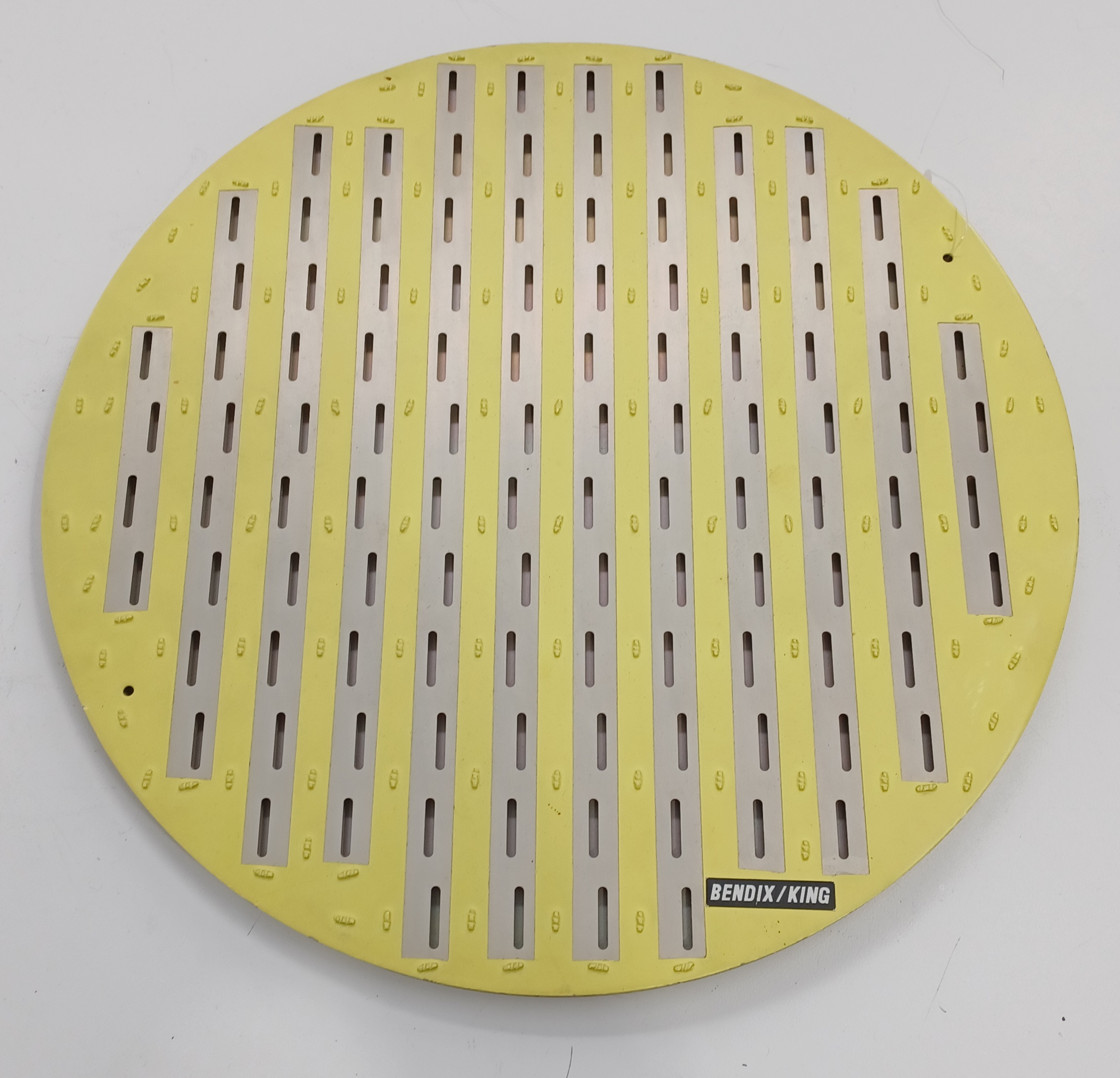.jpg?language_id=1)
These variations are primarily driven by aperture geometry. If you treat a truncated antenna as a round one, the transmitting characteristics remain identical. This ensures that regardless of the specific plate shape required for your aircraft's radome, you receive the same high-resolution beam and reliable hazard detection.
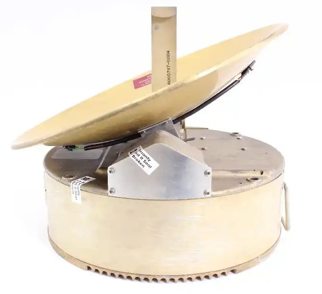
Parabolic reflector antennas use a curved reflective surface to focus microwave energy. A feed horn located at or near the focal point radiates energy back toward the reflector, which then collimates the signal into a narrow, forward-directed beam.
IMPORTANT: When the tilt setting is positive (up), the feed horn moves downward, reflecting the signal upward off the dish. Maintenance technicians must keep this inverted movement in mind during testing.
A solid understanding of antenna architecture helps operators interpret radar displays correctly and allows maintenance personnel to troubleshoot performance issues more effectively.
We are ready to assist you with all your weather radar troubleshooting, repair, or overhaul needs to keep your weather awareness sharp and your flights safe. Reach out to a Duncan Aviation Avionics Component Tech Rep via email at: LNK.ComponentTechReps@DuncanAviation.com.
July 2026
July 2026
July 2026
June 2026
May 2026