In the Dassault Falcon business jet, passenger comfort and flightdeck functionality rely on a seamless ECS (Environmental Control System). At the heart of this system are the Cockpit and Cabin Temperature Sensors. While these components are small, their impact on the flight experience is significant. Checking and cleaning these sensors should be a regular maintenance line item.
These sensors serve as the primary feedback loop for the ECS. Their core function is to provide real-time data to the controllers, allowing the system to regulate air mixing valves and maintain the specific temperature requested by the crew or passengers. For a detailed description, operation, and placement of the units, please refer to your Falcon AMM, Field 6, Chapter 21, Temperature Control, General Description documentation.
To ensure accuracy, these sensors are strategically mounted in high-occupancy areas while remaining protected from direct heat sources. While exact placement can vary slightly by model, they are generally found in the cabin and the flightdeck.
Cabin sensors are usually divided into forward and aft zones. These are often found mounted in the PSU, behind valance panels, within side ledges, or in the aft lavatory/galley areas.
Flightdeck sensors are typically located behind the pilot, on side consoles, ledges, or lower kick panels to monitor the crew environment without interference from avionics heat.
There are several part numbers available. Please refer to the IPC (Illustrated Parts Catalog) and the Fault Isolation Procedure as needed for part applicability.
Each unit features an internal fan. When the system is in Auto mode, these fans rotate to draw a continuous stream of ambient air across the sensing element, ensuring the system responds to the actual cabin or flightdeck environment rather than the temperature of the aircraft’s internal structure.
Despite being located in a pressurized environment, these sensors are prone to accumulating debris. Because the internal fans are constantly pulling air through the unit, often near floor level or upholstery, they act like miniature vacuum cleaners. They are constantly collecting common contaminants, including lint and carpet fibers, dust and particulates, and aerosols.
When these units are overlooked during routine inspections, two primary failures begin to emerge:
Sluggish Response Times: Layers of dust act as an insulator on the sensing element. This physical barrier prevents the sensor from detecting rapid temperature changes, causing the ECS to hunt for the correct setting.
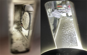
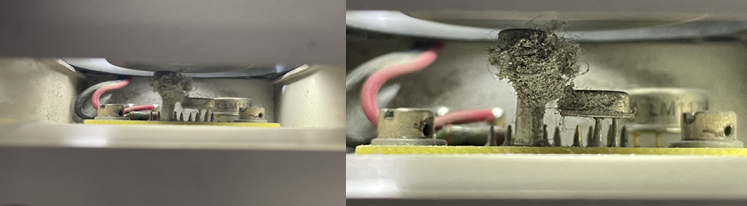
These are examples of extremely dirty cabin sensors. Fan rotation is slowed by excessive contamination.
Inaccurate Temperature Sensing: If the fan is not rotating as designed, either due to mechanical failure or heavy debris buildup, the air around the sensor becomes stagnant. The sensor then reads the temperature of the internal paneling rather than the cabin air, leading to a discrepancy between the requested temperature and the actual cabin feel.
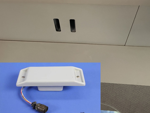
Examples of flightdeck sensors. Handle with care! These sensors contain fragile PC boards and delicate fan blades. Follow the AMM and use only low pressure and a soft artist's brush to clear contaminants without compromising the unit’s integrity.
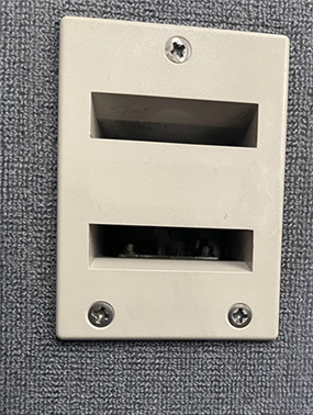
To maintain peak performance, visually check for proper fan rotation when the system is powered and auto-selected. These sensors are often identifiable by small, louvered grilles; a close inspection can confirm if the fan is spinning freely. If the unit appears dirty or the response is degraded, reference the specific Function Test Work Card for approved cleaning procedures.
Handle with care! These sensors contain fragile PC boards and delicate fan blades. Follow the AMM and use only low pressure and a soft artist's brush to clear contaminants without compromising the unit’s integrity.
Keeping these sensors clean is a simple step in ensuring the ECS delivers the precise climate control it was engineered to provide.
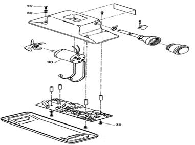
Breakdown of the temperature sensor unit from the Falcon IPC
June 2026
May 2026
May 2026
May 2026
April 2026